Go to file
2018-05-23 17:39:09 +02:00
images Add readme with pin infos and image of the finished board 2018-05-23 17:39:09 +02:00
.gitignore Import sd breakout board 2018-05-14 21:52:09 +02:00
README.md Add readme with pin infos and image of the finished board 2018-05-23 17:39:09 +02:00
sd_breakout-cache.lib Import sd breakout board 2018-05-14 21:52:09 +02:00
sd_breakout.kicad_pcb Import sd breakout board 2018-05-14 21:52:09 +02:00
sd_breakout.pro Import sd breakout board 2018-05-14 21:52:09 +02:00
sd_breakout.sch Import sd breakout board 2018-05-14 21:52:09 +02:00

Mikro-SD Breakout-Platine

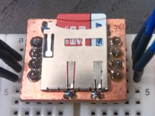
Image of finished breakout board

Pinlayout

              ____________
             |            |
        +----|            |----+
        |    |            |    |
   DAT2 | *  _\           |  * | DAT1
        |    |            |    |
CD/DAT3 | *  \            |  * | DAT0
        |     |           |    |
    CMD | *   |           |  * | GND
        |     |           |    |
    VCC | *   \___________/  * | CLK
        |                      |
        +----------------------+

VCC sollte 3,3V betragen.

SPI-Anschluss

SD SPI ML507 J6-Pin
CLK SCLK 2
CMD MOSI 4
DAT3 CS 6
DAT2 nicht verwendet
DAT1 nicht verwendet
DAT0 MISO 12

Licence

This project by Klemens Schölhorn is licensed under the terms of the GPLv3.